EDM-G-IMX8M TEVS Camera Usage Guide
🚀 Introduction
This article guides you how to get started using TechNexion camera modules on EDM-G-IMX8M Plus/Mini board.
You must have the background knowledge to modify the kernel configuration, rebuild, and replace the kernel and the device tree source (DTS).
This article uses the EDM-G-WB baseboard as an example, based on the Yocto 4.2 (Mickledore) 2024Q2 Release. The corresponding Linux kernel version is 6.1.55_2.2.0.
📸 Supported Camera Modules
- TEVS Series
- VLS3 Series
| Camera Series | Products |
|---|---|
| TEVS | TEVS-AR0144 TEVS-AR0145 TEVS-AR0234 TEVS-AR0521 TEVS-AR0522 TEVS-AR0821 TEVS-AR0822 TEVS-AR1335 |
| Camera Series | Products |
|---|---|
| VLS3 | VLS3-AR0144 VLS3-AR0145 VLS3-AR0234 VLS3-AR0521 VLS3-AR0522 VLS3-AR0821 VLS3-AR0822 VLS3-AR1335 |
TEVI-OV5640 and TEVI-AR Series Cameras are deprecated starting from Yocto 4.2
Support for TEVI-OV5640 and TEVI-AR Series Cameras is available only up to Yocto 4.0.
If you need to use these camera modules, please refer to the 🔗 Yocto 4.0 (Kirkstone) 2024Q1 Release.
🧩 Supported Boards
| SoM | Board |
|---|---|
| EDM-IMX8M-MINI | EDM-G-WB EDM-G-WIZARD |
| EDM-IMX8M-PLUS | EDM-G-WB EDM-G-WIZARD |
🔧 Hardware Setup Instructions
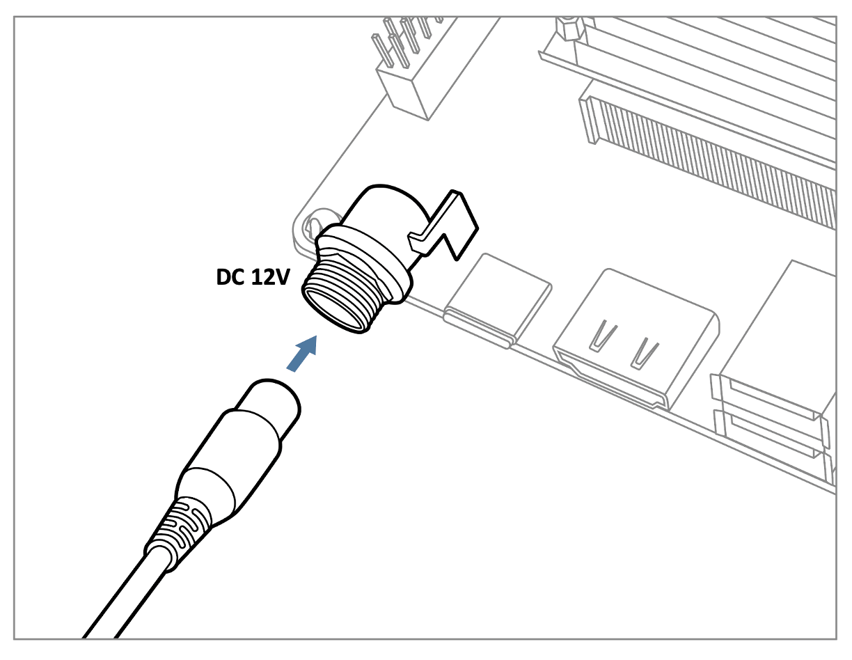
1. Power Supply Preparation
- Use a DC 5V or 12V power cable to supply power to the board.
- If you're using FPD-Link III SerDes, a 12V power adapter (minimum 3A) is required. Connect it via the barrel jack connector.
The EDM-G-WB can also be powered via USB Type-C (5V).
2. Debug Console Connection
- Prepare a USB-to-UART cable if you're connecting to a PC.
- Connect the cable to the debug console port on the EDM-G-WB board.
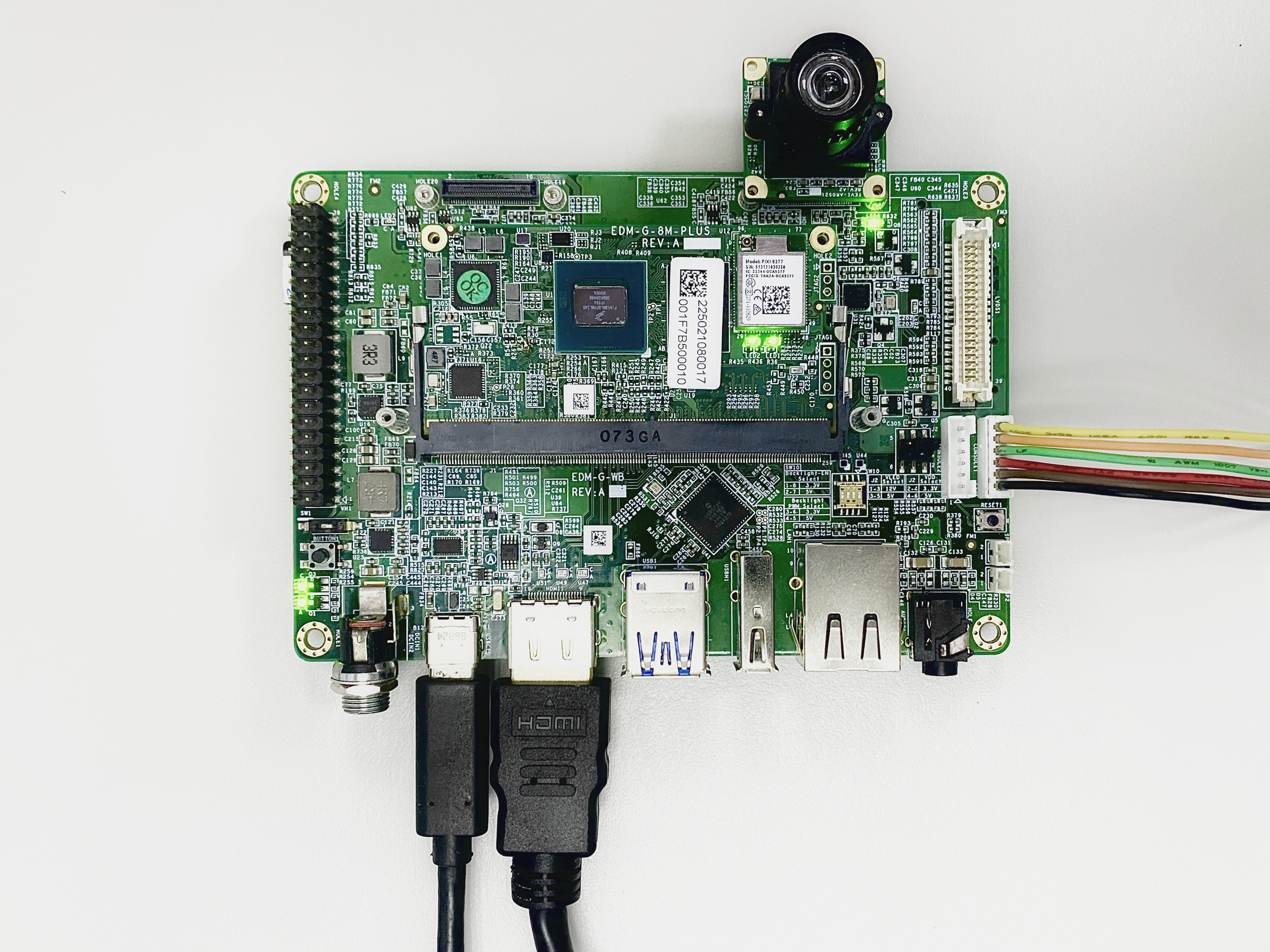
3. Camera Interface (CSI) Overview
- The board features two MIPI-CSI-2 interfaces, referred to as CSI1 and CSI2.
- These use 70-pin board-to-board connectors manufactured by Hirose.
- The image below shows a TEVS camera connected to the CSI1 interface.
💻 Prepare Yocto demo image for testing TechNexion camera
To test TechNexion cameras, you will need a Yocto-based demo image that includes the necessary device tree blobs and camera drivers.
🔽 Downloading the Demo Image
Prebuilt demo images are available for download on TechNexion's official server.
Download Link:
🔗 Supported Release List (Instructions for EDM-G-IMX8MP)
🔗 Supported Release List (Instructions for EDM-G-IMX8MM)
💾 Flashing the Image
You can flash the image to either e.MMC or an SD Card using one of the following methods:
1. Using uuu Tool (Universal Update Utility)
TechNexion provides a guide to flash the image using the uuu tool:
🔗 How to Flash with UUU
Before flashing, ensure the board is set to Serial Download Mode in the boot configuration. You can refer to 🔗 Boot Mode Selection of EDM-G-WB for more details.
2. Using ums Command in U-Boot (USB Mass Storage)
Alternatively, you can write the image directly to flash storage over USB-OTG using U-Boot’s ums command:
🔗 Using UMS in U-Boot
The board must be booted with a version of U-Boot that supports the ums command. Typically, this is done from the existing e.MMC.
🛠️ Build Yocto
TechNexion supports building a Yocto-based Linux image tailored for camera modules using the following kernel and branch.
📦 Supported Linux Kernel
| Linux Kernel Version | Yocto Branch |
|---|---|
| 6.1.55 | tn-imx_6.1.55_2.2.0-stable |
📁 Source and Build Instructions
🔗 Fetch Yocto Source
📖 Build Yocto (Instructions for EDM-G-IMX8MP)
📖 Build Yocto (Instructions for EDM-G-IMX8MM)
📸 Camera Testing Instructions
Specify Camera DTBO in U-Boot
If you are using TEVI AR series or TEVS cameras, you can skip this step. These models support automatic camera detection in U-Boot.
Manual DTBO Setup
-
Connect the debug console cable to the baseboard (via UART).
-
Power on the board and interrupt the boot process. Keep pressing
Enterwhen the following message appears:Hit any key to stop autoboot: -
Set the correct camera overlay (DTBO) using the U-Boot environment variable:
- TEVS Cameras
- VLS3 Cameras
u-boot=> setenv dtoverlay tevs
u-boot=> setenv dtoverlay vls
- Save and continue the boot process:
u-boot=> saveenv
u-boot=> boot
🎥 Start Camera Video Stream via GStreamer
Check Camera Availability
Use the v4l2-ctl tool to list connected video devices.
$ v4l2-ctl --list-device
Example output:
():
/dev/v4l-subdev0
():
/dev/v4l-subdev1

FSL Capture Media Device (platform:32c00000.bus:camera):
/dev/media0

mxc-isi-cap (platform:32e00000.isi:cap_device):
/dev/video0

mxc-isi-cap (platform:32e02000.isi:cap_device):
/dev/video1
In this example, /dev/video0 is the capture device connected via CSI1.
Launch GStreamer Pipeline
Replace <res_w>, <res_h>, <x>, and <y> with your desired resolution and screen dimensions:
$ gst-launch-1.0 v4l2src device=/dev/video0 ! \
  video/x-raw, width=<res_w>, height=<res_h> ! \
  imxvideoconvert_g2d ! \
  waylandsink window-width=<x> window-height=<y> sync=false
imxvideoconvert_g2d is optimized for the i.MX8MP platform and leverages ISI hardware for format conversion.
You may optionally use videoconvert, but it is typically unnecessary.
🚨 Troubleshooting
Ensure camera device tree blob overlay(DTBO) is specified correctly in u-boot.
- TEVS Cameras
- VLS3 Cameras
  u-boot=> printenv dtoverlay
  dtoverlay=tevs
  u-boot=> printenv dtoverlay
  dtoverlay=vls
We can check whether camera have been initialized correctly.
For TEVS cameras:
  $ dmesg -t | grep tevs
    tevs 1-0048: tevs_probe() device node: tevs@48
    tevs 1-0048: Version:24.9.0.1
    tevs 1-0048: Product:TEVS-AR0144, HeaderVer:3, MIPI_Rate:800
    tevs 1-0048: probe success
    mx8-img-md: Registered sensor subdevice: tevs 1-0048 (1)
    mx8-img-md: created link [tevs 1-0048] => [mxc-mipi-csi2.0]
Ensure camera device tree blob(DTB) is specified correctly.
  $ dmesg -t | grep -i model
    Machine model: TechNexion EDM-G-IMX8MP and WB baseboard