WB-EDM-G-IMX8M-PLUS
The WB-EDM-G-IMX8M-PLUS development kit comprises a WB-EDM-G baseboard and an EDM-G-IMX8M-PLUS System-on-Module. The WB-EDM-G Baseboard is a printed circuit board assembly (PCBA) designed to be compatible with TechNexion's EDM-G family of System-on-Modules (SoMs). It has dimensions of 85mm x 125mm and supports various external connectors and peripheral devices.
Overview
| Feature | Description |
|---|---|
| Displays | HDMI + Dual Channel LVDS Output |
| USB Type C | 1x USB 3.0 OTG |
| USB Type A | 2x USB 3.0 Host + 1x USB 2.0 Host |
| Network | 1x 10/100/1000 Ethernet RJ45 jack |
| Camera | 2x MIPI-CSI camera connectors (70-pin Hirose) |
| Audio | On-board stereo audio codec (WM8960), including 3.5mm TRRS headset/mic connector and 2x 8-ohm speaker outputs |
| I/O Expansion | 1x 40-pin header (similar to Raspberry Pi) |
| Console | 2x UART connectors (3.3V TTL/CMOS) |
| SD Card | 1x microSD card slot |
| M.2 Connector | 1x M.2 Key B connector with connected SIM card slot |
| Power Supply | 12VDC via DC barrel jack connector or USB Type C |
Board Pictures
| Top view, with EDM-G-IMX8M-PLUS System-on-Module assembled |
|---|
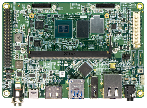 |
| Side view, showing power entry, USB Type C, HDMI, USB Type A, Ethernet, and audio |
|---|
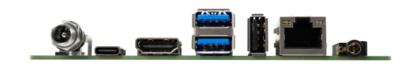 |
| Bottom view, show M.2 slot and microSD card slot |
|---|
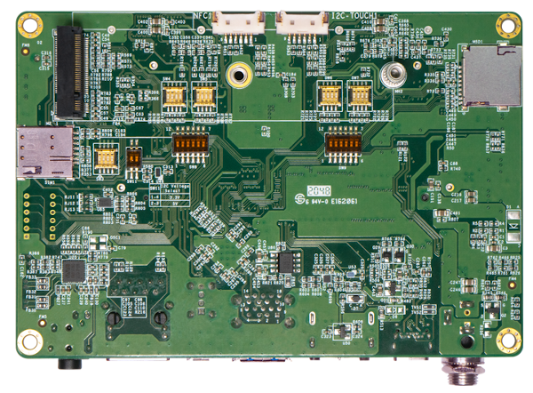 |
Kit Contents
| WB-EDM-G-IMX8M-PLUS Kit Contents |
|---|
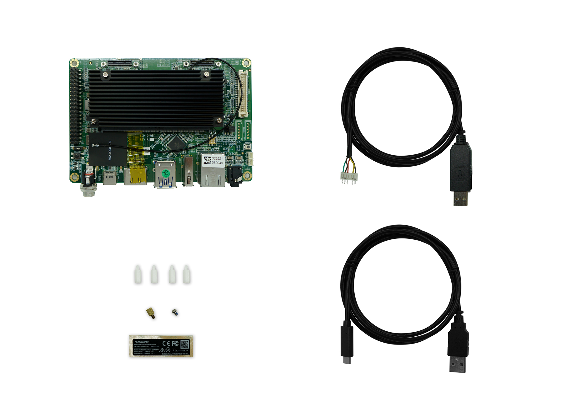 |
The Wandboard EDM-G kits all contain the following:
- Wandboard EDM-G baseboard (WB-EDM-G)
- EDM-G module (based on selection), preassembled with heatsink:
- EDM-G-IMX8M-PLUS
- EDM-G-IMX8M-MINI
- EDM-G-IMX8M-NANO
- Wireless antenna (PCB type)
- USB-UART cable
- USB Type C to Type A cable
- Standoffs, fasteners, and wireless certification decal
Getting Started
| WB-EDM-G-IMX8M-PLUS top view |
|---|
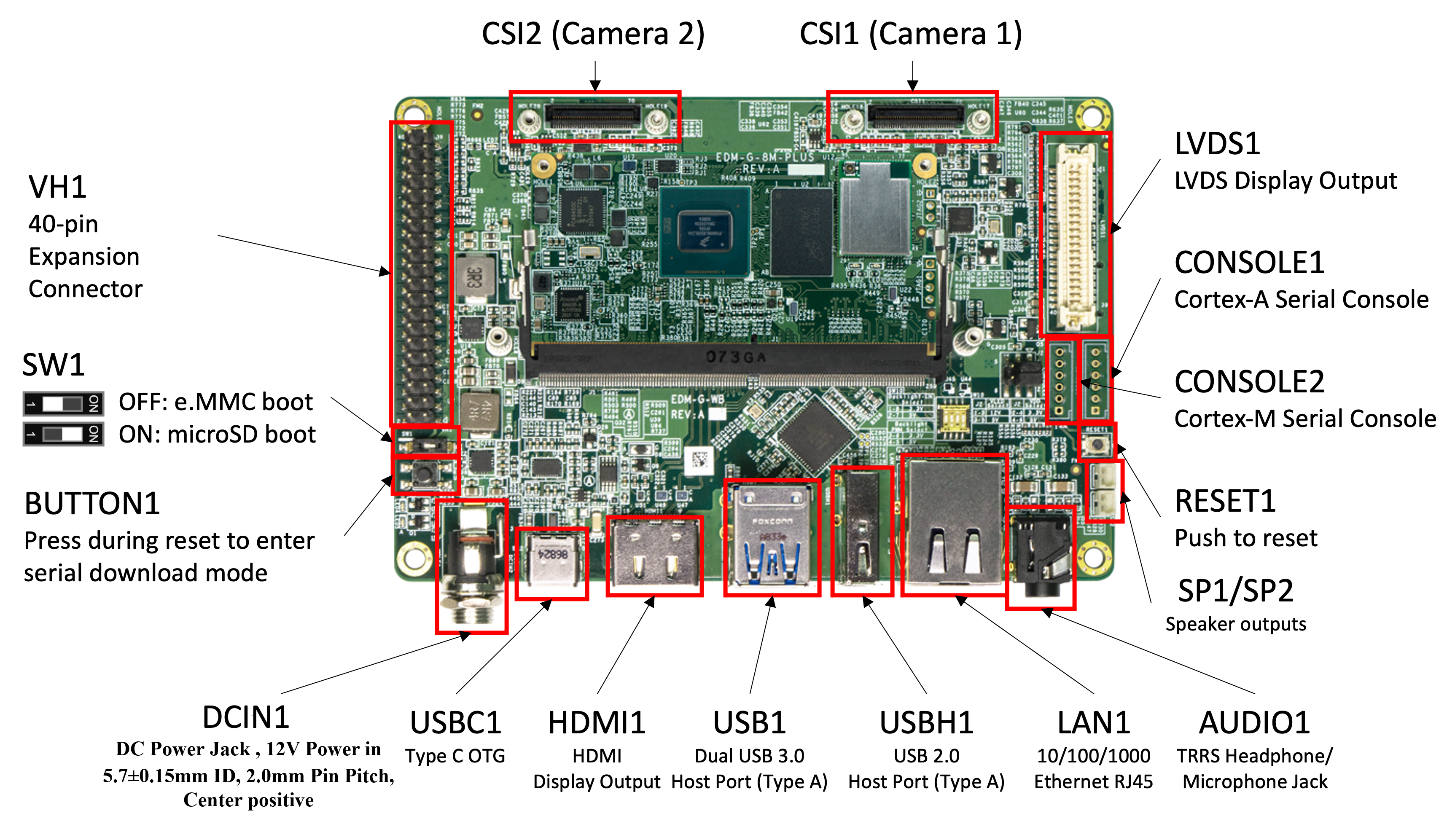 |
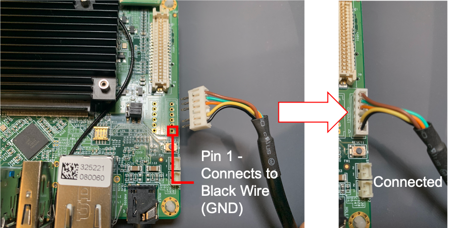
Connecting the Serial Console Cable
The WB-EDM-G kits are supplied with a USB-to-TTL (3.3V) integrated serial console cable. To interact with the main Cortex-A series processor console port, this cable must be connected to CONSOLE1 connector on the WB-EDM-G baseboard.
Board Power
The WB-EDM-G baseboard can be powered either by the USB type C connector (5V), or by the 12V DCIN jack (12V supply sold separately).
A 12V power supply is necessary for connecting an LVDS display or a GMSL2 camera to the board. Additionally, it is recommended when attaching high power-consumption peripherals such as powered USB devices or PCIe NVMe cards to the M.2 slot.DC Power jack information :DCIN1.
[Insert picture here of powering up the board.]
Install Demo Software Images
When your kit arrives, it will be preprogrammed with an image that will assist you in loading software onto the board for the first time. This image is known as the TechNexion Software Loader (or TSL).
The TSL connects the kit to an internet-connected network via the Ethernet port. It operates as a graphical user interface application and functions optimally when used with an attached display, such as the LVDS touchscreen kit. Alternatively, an HDMI display can be used, but a USB mouse must be connected to one of the USB ports.
Display Option 1: HDMI
Connect an HDMI cable for your display into the WB-EDM-G baseboard's HDMI connector. Note that a USB keyboard and mouse is required to navigate the TSL menu options.
Display Option 2: Attaching the 10.1' LVDS display kit
The LVDS display kit (available separately) is attached to the WB-EDM-G baseboard using the LVDS connector LVDS1. The touchscreen interface is connected using a 6-pin wafer connector on the bottom of the PCB.
Step 1: Insert the low-insertion force connection into the LVDS display kit as shown:
[Insert image here showing the display cable connection to the LVDS display]
Step 2: Connect the LVDS cable into the WB-EDM-G kit as shown:
[Insert image here showing the LVDS display cable connection to the WB-EDM-G baseboard]
Step 3: Insert the touchscreen cable into the LVDS display kit as shown below:
[Insert image here showing the how to connect touchscreen connector on back of 10'1 LVDS display kit]
Step 4: Insert the touchscreen cable into the WB-EDM-G baseboard:
[Insert image here showing how to connect the touchscreen cable]
On the bottom of the PCB, there are two 6-pin connectors that are identical. Connect the touchscreen cable into the one labelled TOUCH1. The other connector is reserved for use by an NFC development kit.
[Insert image here pointing to the connector touch connector]
The TSL will guide you through a series of screens, enabling you to choose the type of image (Yocto, Debian, or Android) and the storage location (e.g. eMMC, SD card).
[Insert image here showing TSL running on WB-EDM-G baseboard]
Additional Demo Images
If you want to download additional demo images, you can easily do this by navigating your browser to our download server. We usually update these 2-3 times a year as we release updated BSPs.
Download Additional EDM-G-IMX8MP Demo Images
Flashing e.MMC
During development or initial manufacturing, you may want to flash the entire e.MMC. Or, you way want to recover a 'bricked' unit (one that will not boot). To do this, you can follow our step-by-step tutorial showing how to use the uuu tool here:
If the board boots, and you have access to a serial console, you may want to use U-boot's ums command to load software to the e.MMC:
Using U-boot's 'ums' command to flash e.MMC
Recovery to Factory Settings
It may be necessary or desireable to recover the unit to factory settings. For example, you may want to use the Technexion Software Loader to download and install a different demo image to the board.
The process for doing this is identical to flashing a regular Linux image to your board, except that you would need to download the TechNexion Software Loader (TSL) image instead.
| Download Software Loader Image |
|---|
| EDM-G-IMX8M-PLUS - HDMI or LVDS display |
| EDM-G-IMX8M-MINI - LVDS display |
Boot Media Selection Switch
There are two primary boot media selection settings on the Wandboard EDM-G: boot from e.MMC and boot from the baseboard microSD card. These settings are controlled using the DIP switch SW1. When SW1 is OFF, the board will boot from e.MMC. Conversely, when SW1 is ON, the board will boot from the baseboard microSD card.
Note the default boot media is EMMC
Boot Mode Selection Button
There are two main boot modes: Normal boot, where the SOC boots from either e.MMC or microSD card (determined by the SW1 setting), and serial download mode. Serial download mode is useful when reprogramming a blank e.MMC or completely overwriting the e.MMC without needing to run a serial console.
To boot into serial download mode, press and hold BUTTON1 while pressing RESET1 (reset pushbutton switch).
Boot Media and Boot Mode election
| Mode | Setting |
|---|---|
| EMMC | 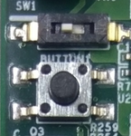 |
| microSD (on baseboard) | 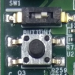 |
| Serial download mode | 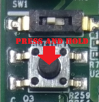 |
Documentation
Refer to the SoM product page’s Documentation section for details on the development kit. It includes schematics for all baseboards and PCB files.
EDM-G-IMX8M-PLUS - technexion.com
Support
Having trouble? Please check out our support page for available support options.