EDM-IMX95-EVM
The EDM-IMX95-EVM development kit comprises a IMX95-EVM baseboard and an EDM-IMX95 System-on-Module. The IMX95-EVM baseboard is a printed circuit board assembly (PCBA) designed to be compatible with TechNexion's EDM family of System-on-Modules (SoMs). It is a larger (150mm x 150mm) and more full-featured development kit for the EDM-IMX95 System on Module.
Overview
| Feature | Description |
|---|---|
| Displays | Dual Channel LVDS Output + MIPI-DSI |
| USB Type C | 1x USB 3.0 OTG |
| USB Type A | 2x USB 2.0 Host |
| Network | 2x 10/100/1000 Ethernet RJ45 jack |
| Camera | 2x MIPI-CSI camera connectors (70-pin Hirose) |
| Audio | On-board stereo audio codec, including 3.5mm TRRS headset/mic connector and a line out connector |
| I/O Expansion | 1x 20-pin header + 1x SPI 6-pin header + 2x CAN-FD 4-pin connectors |
| Console | 3x UART connectors (3.3V TTL/CMOS) |
| SD Card | 1x microSD card slot |
| M.2 Connector | 1x M.2 B-Key connector with connected SIM card slots + 2x M.2 M-Key connectors |
| RS-232 | 1x DB-9 connector |
| Power Supply | 12VDC via DC barrel jack connector |
Board Pictures
| Top view, with EDM-IMX95 System-on-Module assembled |
|---|
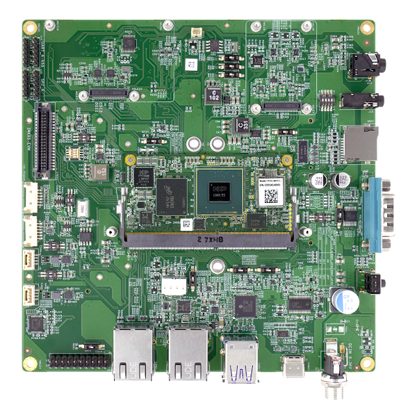 |
| Side view, showing power entry, USB Type C, USB Type A and Ethernet |
|---|
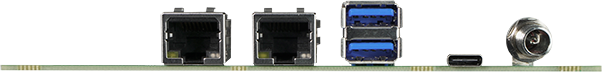 |
| Bottom view, show MIPI-CSI connector, M.2 slot and microSD card slot |
|---|
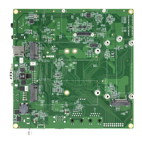 |
Kit Contents
| Kit View, showing cables and accessories |
|---|
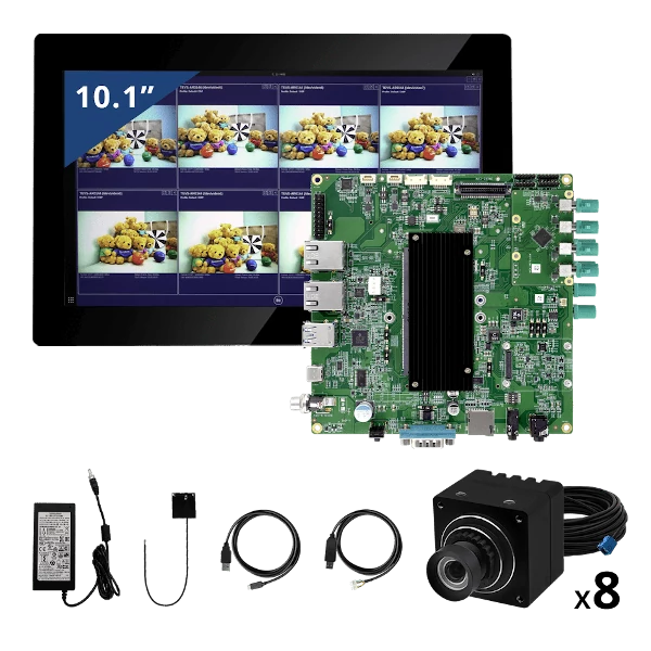 |
The Multicamera Enablement Kit (MEK) all contain the following:
- EVM EDM baseboard (IMX95-EVM)
- EDM-IMX95 Module
- Wireless antenna (PCB type)
- USB-UART cable
- USB Type C to Type A cable
- 10.1” LVDS display
A 12V power supply, sold separately, is required to power the EDM-IMX95-EVM kit.
Getting Started
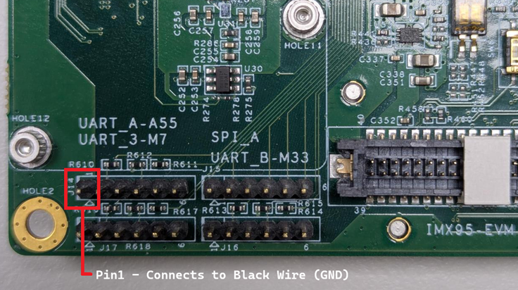
Connecting the Serial Console Cable
The EDM-IMX95 kits are supplied with a USB-to-TTL (3.3V) integrated serial console cable. To interact with the main Cortex-A series processor console port, this cable must be connected to UART_A-A55 connector on the IMX95-EVM baseboard.
Board Power
The IMX95-EVM baseboard is powered by the 12V DCIN jack (12V supply sold separately).
A 12V power supply is necessary for connecting an LVDS display or a GMSL2 camera to the board. Additionally, it is important when attaching high power-consumption peripherals such as powered USB devices or PCIe NVMe cards to the M.2 slot.DC Power jack information :DCIN1.
Install Demo Software Images
When your kit arrives, it will be preprogrammed with an image that will assist you in loading software onto the board for the first time. This image is known as the TechNexion Software Loader (or TSL).
The TSL connects the kit to an internet-connected network via the Ethernet port. It operates as a graphical user interface application and functions optimally when used with an attached display, such as the LVDS touchscreen kit.
The TSL will guide you through a series of screens, enabling you to choose the type of image (Yocto, Debian, or Android) and the storage location (e.g. eMMC, SD card).
Additional Demo Images
If you want to download additional demo images, you can easily do this by navigating your browser to our download server. We usually update these 2-3 times a year as we release updated BSPs.
Download Additional EDM-IMX95 Demo Images
Boot Media Selection Switch
There are two primary boot media selection settings on the IMX95-EVM: boot from e.MMC and boot from the baseboard microSD card. These settings are controlled using the DIP switch SW17. When SW17 is OFF, the board will boot from e.MMC. Conversely, when SW17 is ON, the board will boot from the baseboard microSD card.
Note the default boot media is EMMC
Boot Mode Selection Button
There are two main boot modes: Normal boot, where the SOC boots from either e.MMC or microSD card (determined by the SW17-1 setting), and serial download mode. Serial download mode is useful when reprogramming a blank e.MMC or completely overwriting the e.MMC without needing to run a serial console.
To boot into serial download mode, change DIP switch SW17-2 to ON. When SW17-2 is ON, the state of SW17-1 does not matter. A power on reset (POR) or a manual reset are required after changing the SW17 DIP switch settings.
Boot Media and Boot Mode election
| Mode | Setting |
|---|---|
| EMMC | 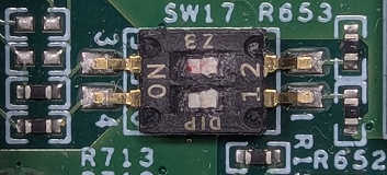 |
| microSD (on baseboard) | 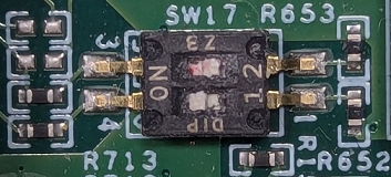 |
| Serial download mode |  |
Documentation
Refer to the SoM product page’s Documentation section for details on the development kit. It includes schematics for all baseboards and PCB files.
Support
Having trouble? Please check out our support page for available support options.