Introduction to DC Power Jack and Mating DC Plug Diagrams
DC Power Jack and Mating DC Plug Diagrams
This section provides mechanical reference diagrams for the DC power jack and its mating connector (DC plug). The figures are intended to help verify connector compatibility, panel/enclosure clearance, and installation constraints during system integration. All dimensions are specified in millimeters (mm). When designing the chassis cutout or mounting position, please reserve adequate space for the connector body, the plug housing/strain relief, and the cable routing direction to avoid mechanical interference or excessive bending stress.
DC Power Jack Diagram
The following diagram illustrates the mechanical dimensions of the DC power jack, including the threaded barrel specification and the plug insertion depth. These values are useful for determining panel thickness limits, nut/washer engagement, and the minimum clearance required for proper plug seating.
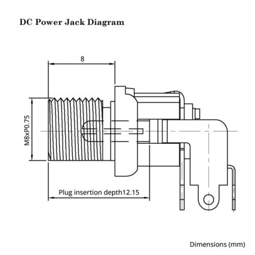
Key Dimensions (mm)
- Thread specification: M8 × P0.75
- Threaded barrel length: 8
- Plug insertion depth: 12.15
Notes
- The plug insertion depth indicates the minimum mating length required for the plug to fully seat inside the jack.
- Ensure the threaded barrel length provides sufficient engagement for the mounting hardware (nut/washer) based on your panel thickness.
- Leave additional clearance around the jack body and along the insertion direction to prevent collisions with enclosure ribs, brackets, or neighboring components.
DC Power Connector (plug): Male Diagram
The diagram below shows the mechanical outline of the DC jack male plug and highlights the key mating dimensions for the corresponding DC plug. This information is used to confirm that the plug dimensions match the jack geometry and that the plug body can be inserted without obstruction.
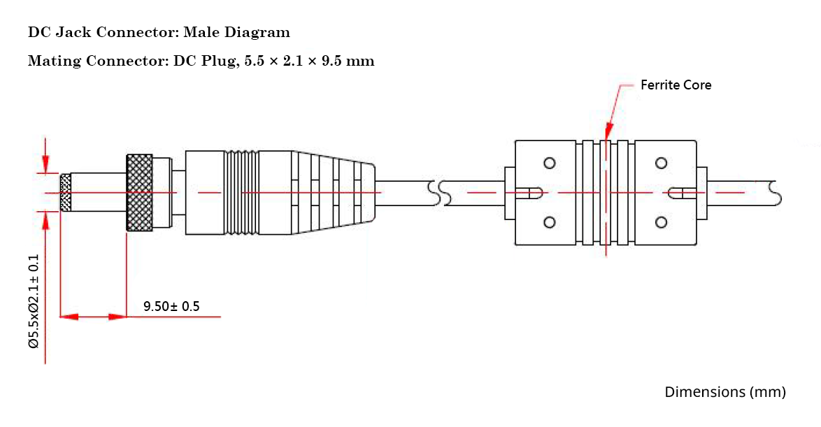
Mating Connector
- DC Plug: 5.5 × 2.1 × 9.5 mm
Key Dimensions (mm)
- Outer diameter (OD): Ø5.5 ± 0.1
- Inner diameter (ID): Ø2.1 ± 0.1
- Plug length / insertion reference: 9.5 ± 0.5
Notes
- The 5.5 × 2.1 mm specification refers to the plug’s outer/inner barrel diameters, which must match the jack contact geometry for stable electrical contact.
- The 9.5 mm length indicates the approximate plug barrel length used for mating; confirm the plug can fully seat considering panel thickness and internal mechanical constraints.
- The diagram indicates a ferrite core on the cable, which is commonly used to reduce EMI; reserve sufficient space along the harness path if the ferrite core must pass through cable clamps or guides.