IMX8MM Camera Usage Guide
🚀 Introduction
This guide shows you how to get started using TechNexion camera modules on TechNexion IMX8MM development kits. You must have the background knowledge to modify the kernel configuration, rebuild, and replace the kernel and the device tree source (DTS). This article is based on the 🔗 Yocto 5.0 (Scarthgap) 2026Q1 Release with Linux kernel version 6.6.52-2.2.2.
📸 Supported Camera Modules
- TEVS Series
- TEVM Series
| Camera Series | Products |
|---|---|
| TEVS | TEVS-AR0144 TEVS-AR0145 TEVS-AR0234 TEVS-AR0235 TEVS-AR0246 TEVS-AR0521 TEVS-AR0522 TEVS-AR0544 TEVS-AR0821 TEVS-AR0822 TEVS-AR0830 TEVS-AR1335 TEVS-AR2020 |
| Camera Series | Products |
|---|---|
| TEVM | TEVM-AR0144 TEVM-AR0145 TEVM-AR0234 TEVM-AR0235 TEVM-AR0246 TEVM-AR0521 TEVM-AR0522 TEVM-AR0544 TEVM-AR0821 TEVM-AR0822 TEVM-AR0830 TEVM-AR1335 TEVM-AR2020 |
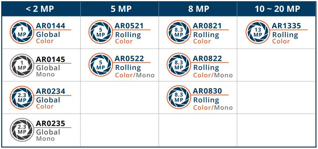
This article uses the TEVS-AR0144 as an example.
🧩 Supported Boards
| SoM | Board |
|---|---|
| EDM-G-IMX8M-MINI | WB-EDM-G-IMX8M-MINI |
| PICO-IMX8M-MINI | PICO-PI-IMX8M-MINI PICO-WIZARD-IMX8M-MINI |
🔧 Hardware Setup Instructions
1. Power Supply Preparation
- Use a DC 5V or 12V power cable to supply power to the board.
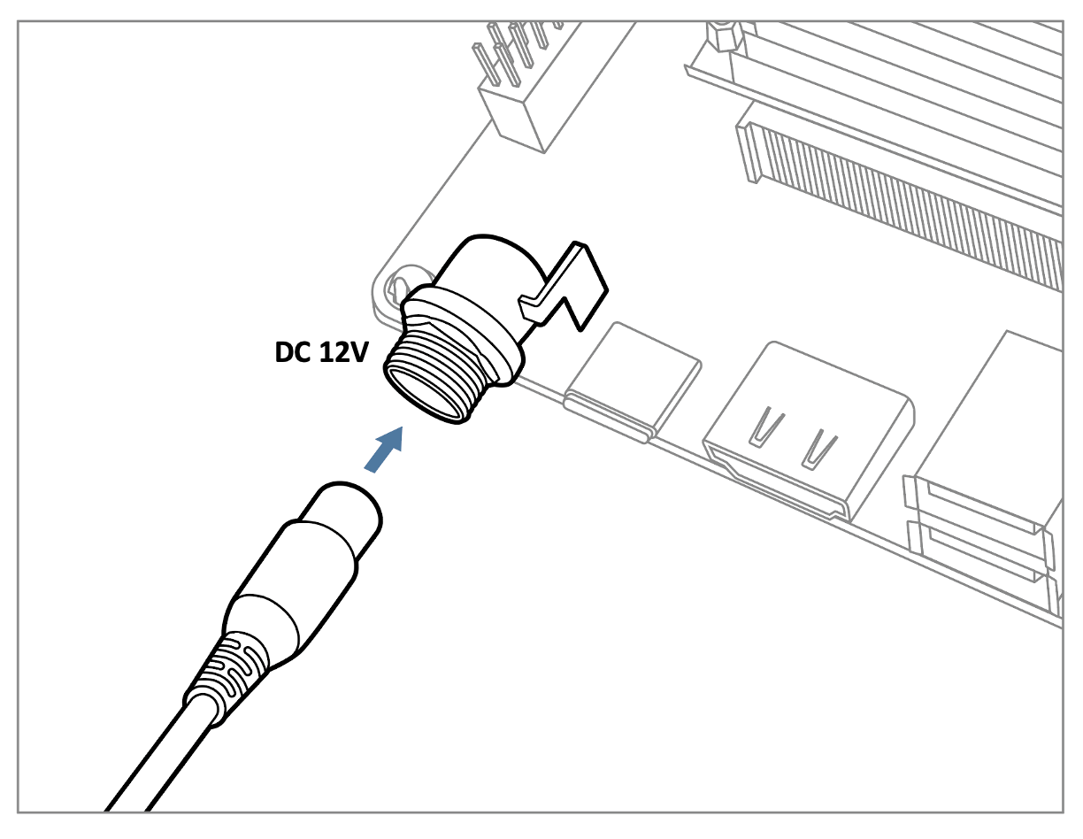
- If you're using FPD-Link III SerDes, a 12V power adapter (minimum 3A) is required. Connect it via the barrel jack connector.
2. Debug Console Connection
- Prepare a USB-to-UART cable if you're connecting to a PC.
- Connect it to the CONSOLE1 connector.
3. Display Output Connection
- Prepare a panel for output display.
- Connect the panel to the LVDS1 connector on the board.
The provided DTBs include configuration for 10.1-inch and 15.6-inch LVDS display panels, as well as a 5-inch MIPI panel.
This allows the system to output video, which is useful for verifying camera streaming on screen.
4. Camera Interface (CSI) Overview
- The board features one MIPI CSI-2 interface, referred to as CSI1.
- This uses a 70-pin board-to-board connector manufactured by Hirose.
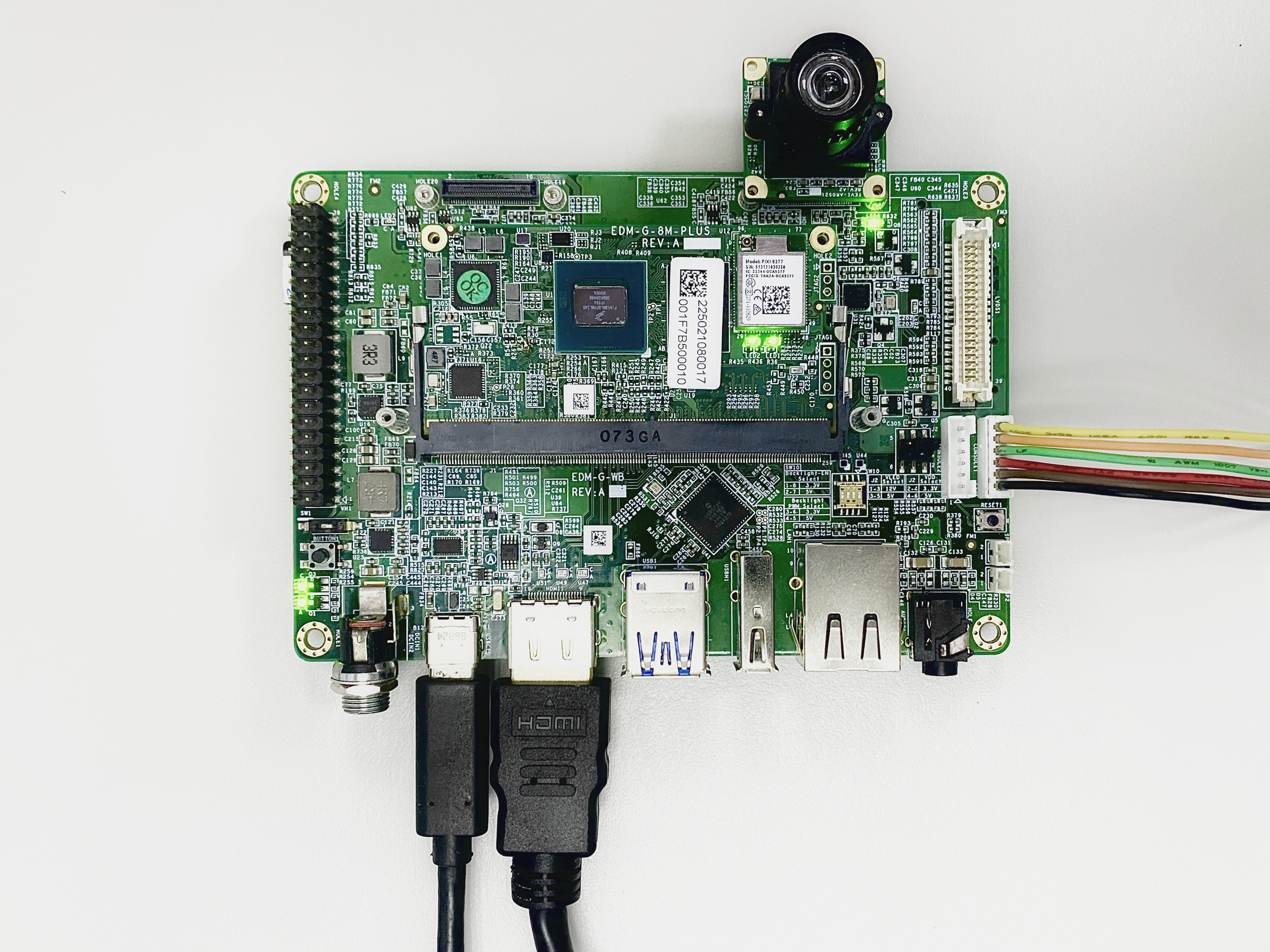
Although the board has two CSI interfaces, only CSI1 is enabled. The IMX8M-MINI only supports one MIPI CSI-2 interface.
💻 Prepare Yocto demo image for testing TechNexion camera
To test TechNexion cameras, you will need a Yocto-based demo image that includes the necessary device tree blobs and camera drivers.
🔽 Downloading the Demo Image
We provide a pre-built demo image to simplify using TEVS cameras, available for download on TechNexion's official server.
Download Link:
- EDM-G-IMX8MM
- PICO-IMX8MM
💾 Flashing the Image
You can flash the image to either e.MMC or an SD Card using one of the following methods:
Method 1. Using uuu Tool (Universal Update Utility)
TechNexion provides a guide to flash the image using the uuu tool:
🔗 How to Flash with UUU
Before flashing, ensure the board is set to Serial Download Mode in the boot configuration.
Method 2. Using ums Command in U-Boot (USB Mass Storage)
Alternatively, you can write the image directly to flash storage over USB-OTG using U-Boot’s ums command:
🔗 Using UMS in U-Boot
The board must be booted with a version of U-Boot that supports the ums command. Typically, this is done from the existing e.MMC.
Method 3. For Windows Users
Use balenaEtcher to write the image to your SD card:
🔗 Using Balena Etcher

🛠️ Build Yocto
TechNexion supports building a Yocto-based Linux image tailored for camera modules using the following kernel and branch.
If you are using prebuilt demo image, you can skip this section. Please refer to 📸 Camera Testing Instructions section for camera testing steps.
📦 Supported Linux Kernel
| Linux Kernel Version | Yocto Branch |
|---|---|
| 6.6.52 | tn-imx_6.6.52_2.2.2-stable |
📁 Source and Build Instructions
- EDM-G-IMX8MM
- PICO-IMX8MM
📸 Camera Testing Instructions
🌳 Specify Camera DTBO in U-Boot
- Connect the debug console cable to carrier board.
- Power on the board and interrupt the boot process. Keep pressing
Enterwhen the following message appears:Hit any key to stop autoboot: - Specify the appropriate device tree for your camera using the
fdtfileenvironment variable in U-Boot:
- CSI1 connector
u-boot=> setenv dtoverlay tevs- Continue boot process.
u-boot=> saveenv
u-boot=> boot
The vxt-vl050-070-8048nt overlay is for the 5-inch LCD display panel. If you want to see the camera output on screen, append the display overlay together with the camera overlay.
e.g.
u-boot=> setenv dtoverlay=tevs vxt-vl050-070-8048nt🎥 Start Camera Video Stream via GStreamer
Launch GStreamer Pipeline
Specify the capture device you just get and start GStreamer to get the video stream on screen. Replace <res_w> and <res_h> with your selected resolution(1280x720) and screen dimensions.
$ gst-launch-1.0 v4l2src device=/dev/video0 ! \
  "video/x-raw, format=UYVY, width=1280, height=720" ! \
  waylandsink sync=false
🚨 Troubleshooting
Check DTB Overlay in U-Boot
Make sure the correct Device Tree Blob (DTB) is specified in U-Boot.
- CSI1 connector
u-boot=> printenv dtoverlay
dtoverlay=tevs vxt-vl050-070-8048nt
The vxt-vl050-070-8048nt overlay is for the 5-inch LCD display panel.
Verify Camera Initialization
Use dmesg to check if the TEVS camera module was initialized correctly.
$ dmesg -t | grep tevs
    platform 32e30000.mipi_csi: Fixed dependency cycle(s) with /soc@0/bus@30800000/i2c@30a30000/tevs_mipi@48
    tevs 1-0048: tevs_probe() device node: tevs_mipi@48
    tevs 1-0048: Version:26.3.0.1
    tevs 1-0048: Product:TEVS-AR0144, HeaderVer:3, MIPI_Rate:800
    tevs 1-0048: Chip ID: 0x0356
    mxc_mipi-csi 32e30000.mipi_csi: Registered sensor subdevice: tevs 1-0048
    tevs 1-0048: probe success
Confirm Board and Camera DTB
Check if the correct DTB is loaded with a matching camera model.
- EDM-G-IMX8MM
- PICO-IMX8MM
$ dmesg -t | grep -i model
Machine model: TechNexion EDM-G-IMX8MM and WB baseboard
$ dmesg -t | grep -i model
Machine model: TechNexion PICO-IMX8MM and PI baseboardCheck Available Video Devices
Verify that the video devices are available.
$ v4l2-ctl --list-device
Example output:
i.MX6S_CSI (platform:32e20000.csi1_bridge):
        /dev/video0

vsi_v4l2dec (platform:vsi_v4l2dec):
        /dev/video2

vsi_v4l2enc (platform:vsi_v4l2enc):
        /dev/video1
Typically, /dev/video0 is your primary camera capture device when using CSI1.