Overview
This article provides a visual and technical overview of the schematics to help developers better understand the internal architecture and interfaces of our products.
If you are using legacy camera hardware or earlier RPI adapters, see the Legacy MIPI CSI-2 Overview.
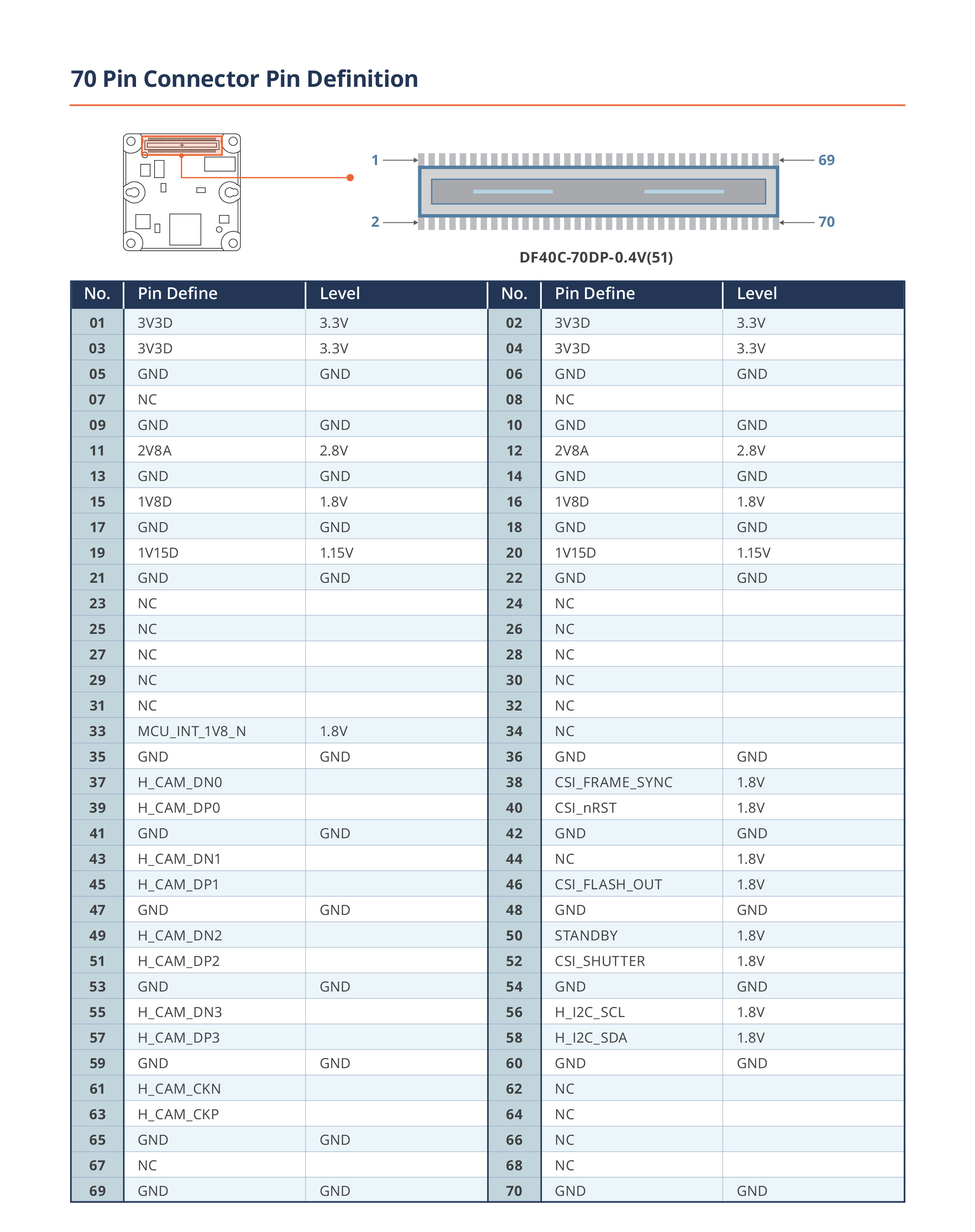
Camera Pin Defintion
| TEVS/TEVM Series |
|---|
 |
15-pin connectors
| TEVS/TEVM-RPI15 |
|---|
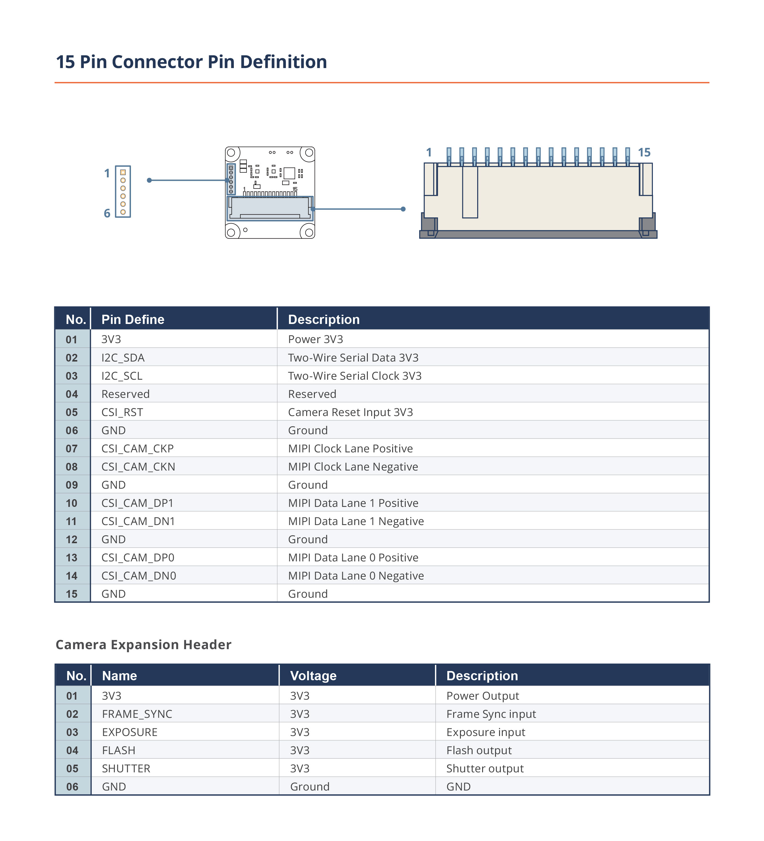 |
IO Expander Pin definition (I2C Address: 0x21)
| No. | Pin Define | Description |
|---|---|---|
| 0 | Reserved | Reserved pin |
| 1 | Reserved | Reserved pin |
| 2 | STANDBY | Standby pin of TEVS/TEVM Camera |
| 3 | Reserved | Reserved pin |
| 4 | CSI_FRAME_SYNC | Framesync Trigger pin of TEVS/TEVM Camera |
| 5 | Reserved | Reserved pin |
| 6 | Reserved | Reserved pin |
| 7 | Reserved | Reserved pin |
22-pin connector
| TEVS/TEVM-RPI22 |
|---|
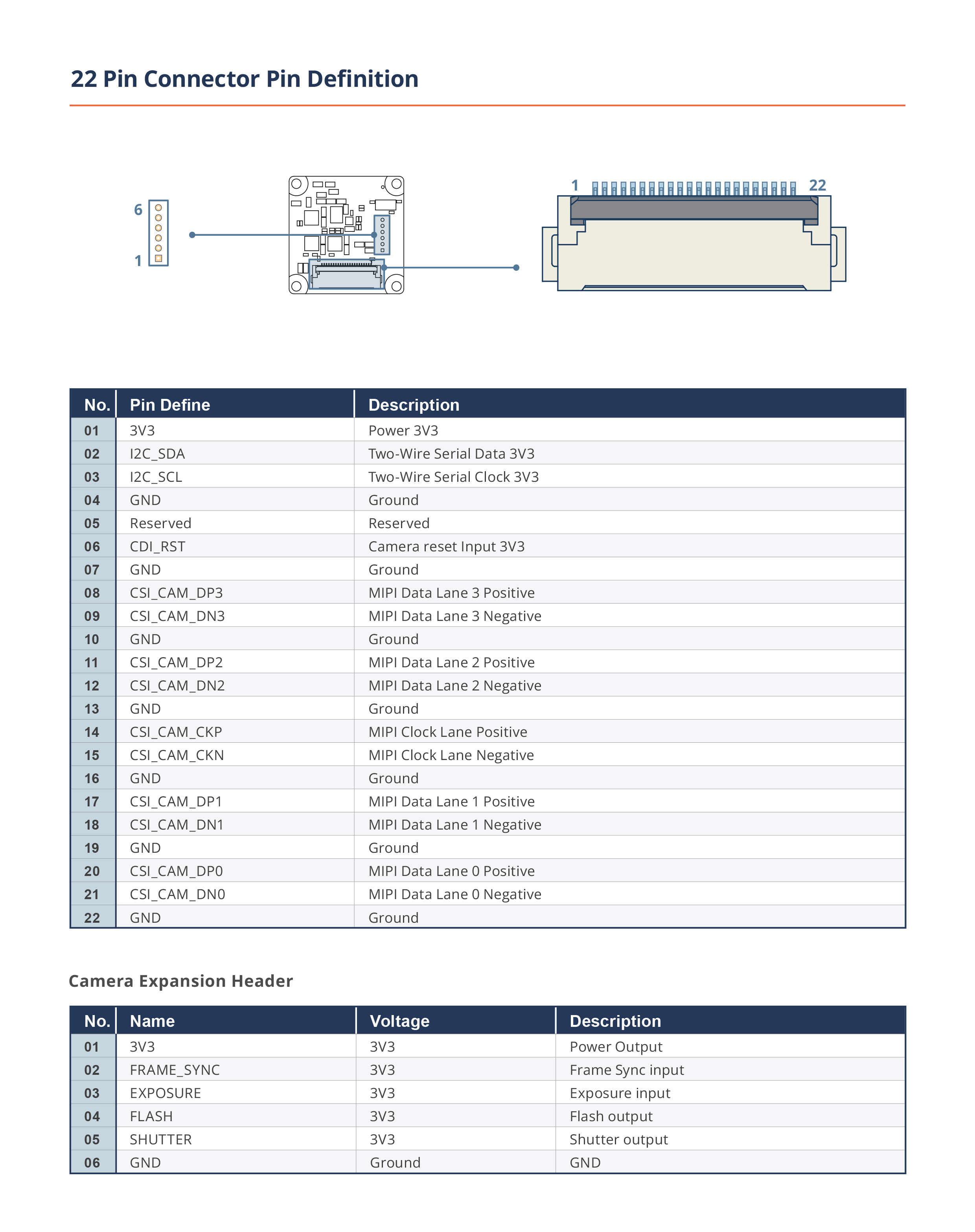 |
IO Expander Pin definition (I2C Address: 0x27)
| No. | Pin Define | Description |
|---|---|---|
| 0 | Reserved | Reserved pin |
| 1 | Reserved | Reserved pin |
| 2 | Reserved | Reserved pin |
| 3 | CSI_FRAME_SYNC | Framesync Trigger pin of TEVS/TEVM Camera |
| 4 | Reserved | Reserved pin |
| 5 | Reserved | Reserved pin |
| 6 | STANDBY | Standby pin of TEVS/TEVM Camera |
| 7 | Reserved | Reserved pin |
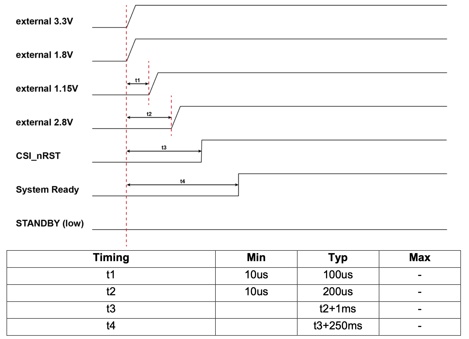
TEVS/TEVM Series Power Up Sequence
Apply 3.3 V and 1.8 V first. After t1 enable 1.15 V. After t2 enable 2.8 V while keeping CSI_nRST asserted low. Pull CSI_nRST high after t3 once all rails and the reference clock are stable. The module then asserts System Ready after t4, indicating the host can begin I²C initialization and start MIPI streaming. Keep STANDBY at low level throughout startup.
TEVS/TEVM Series Power Requirements
The following recommendations are for a power supply scheme suitable for use with any TEVS/TEVM camera. Actual camera power consumption will vary depending on the specific sensor and usage scenario.
| Supply | Voltage | Maximum Current |
|---|---|---|
| 3V3D | 3.3V | 1.2A |
| 2V8A | 2.8V | 600mA |
| 1V8D | 1.8V | 600mA |
| 1V15D | 1.15V | 600mA |
For supply reference designs, please refer to schematics for any TechNexion SOM development kit including those for EDM, EDM-G, AXON, and PICO modules.
Camera with IMU
TEVM cameras include an onboard IMU. Use the shared TEVS/TEVM power sequence, power requirements, MIPI CSI-2 interface, and adapter setup. To access IMU data, open the camera through VizionSDK, enable the IMU mode, then read the accelerometer, gyroscope, ISPU, or temperature data as needed.
For detailed API usage, see Camera IMU.
Need more Help?
If you have questions about the schematics or how to use them for your development work, feel free to reach out via:
- Contact Email: sales@technexion.com