Understanding VL-GM2-AGX-8CAM Adaptor with Jetson AGX Orin
Overview
This article mainly describes the status of the VL-GM2-AGX-8CAM adaptor and how to use the additional 20-pin connector.
LEDs
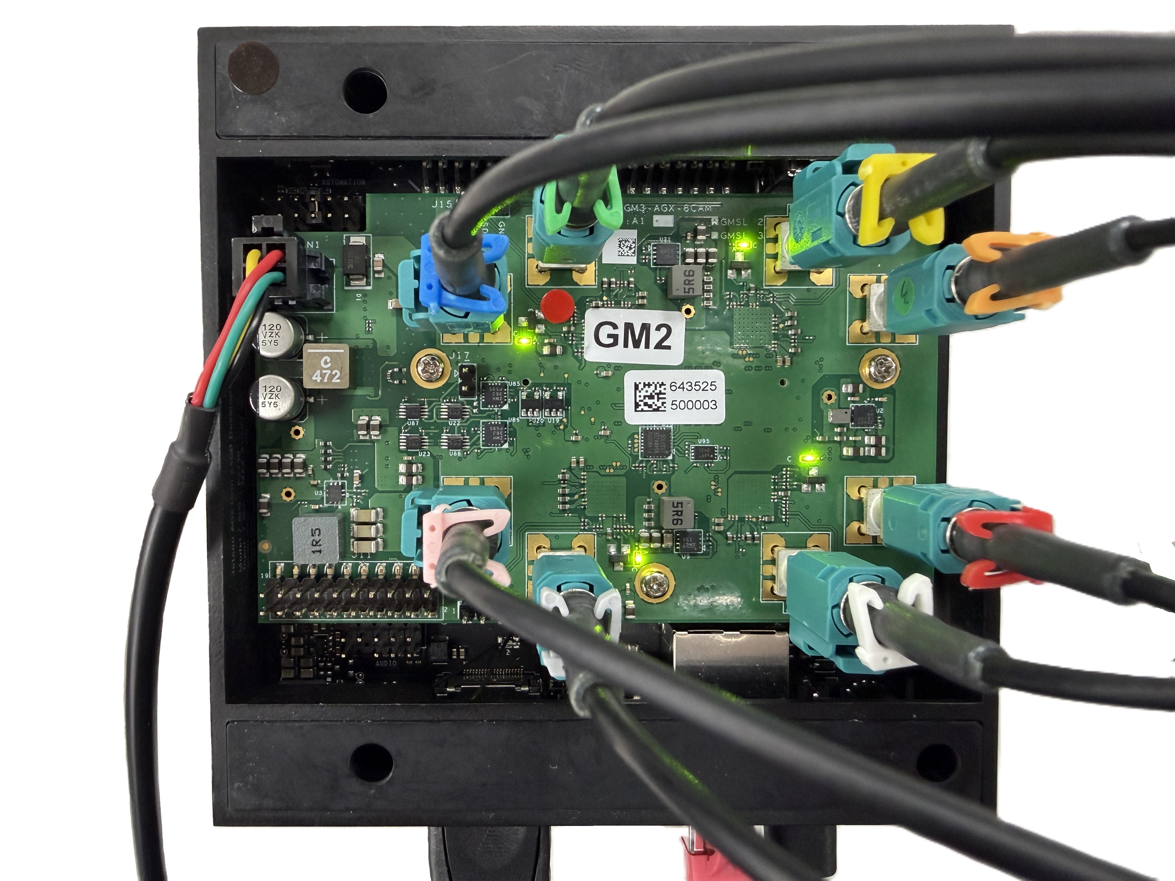
The VL-GM2-AGX-8CAM adaptor has four LED indicators, as shown in picture below. All green LEDs are the lock indicator lights for the four Deserializers, respectively.
Power Selector
The VL-GM2-AGX-8CAM adaptor can support multiple input power, accepting 12V from the DC jack or 5V from the additional pin connector.
The 5V input power supply only supports a maximum current of 2A. If you want to connect multiple or eight VLS-GM2 cameras, we still recommend using a 12V input power supply.
Additional 20 Pin Connector
When using TechNexion VL-GM2-AGX-8CAM adaptor, it has an additional 20 pin connector that can be connected to the 40 pin connector of the Jetson AGX Orin.
How to connect to AGX Orin
| Adaptor [Pin Num] | AGX Orin [Pin Num] |
|---|---|
| 5V [2] | 5V [2] |
| 5V [4] | 5V [4] |
| GND [6] | GND [6] |
| GND [9] | GND [9] |
| GND [14] | GND [14] |
| EXT_SYNC_IN [19] | GPIO12(PWM) [15] |
| GND [20] | GND [20] |
In the adaptor, EXT_SYNC_IN is the deserializer's external frame sync signal pin, which can be used with the fsync-external device tree. Users can input a PWM signal to synchronize the four deserializers.
External Frame Sync Singal
The pin number 15 is PWM0 on the 40 pin connector of the Jetson AGX Orin.
You can use the following shell script to set PWM0 to a 30Hz signal with a 50% duty cycle.
echo 0 > /sys/class/pwm/pwmchip0/export
sleep 0.1
echo 33333333 > /sys/class/pwm/pwmchip0/pwm0/period
echo 16666666 > /sys/class/pwm/pwmchip0/pwm0/duty_cycle
sleep 0.1
echo 1 > /sys/class/pwm/pwmchip0/pwm0/enable
Troubleshooting
-
Host MIPI CSI-2 can't get image from GMSL2
You can use I2C commands to reset the serializer MIPI channel data to ensure MIPI data alignment. The example is as follows.
I2CBUS_0=9
SER_0=0x41
SER_1=0x42

echo '[   INFO ] Reset serializer index 0 to 1 mipi rx'
i2ctransfer -f -y $I2CBUS_0 w3@$SER_0 0x03 0x30 0x48
i2ctransfer -f -y $I2CBUS_0 w3@$SER_1 0x03 0x30 0x48
i2ctransfer -f -y $I2CBUS_0 w3@$SER_0 0x03 0x30 0x40
i2ctransfer -f -y $I2CBUS_0 w3@$SER_1 0x03 0x30 0x40

I2CBUS_1=10
SER_2=0x41
SER_3=0x42

echo '[   INFO ] Reset serializer index 2 to 3 mipi rx'
i2ctransfer -f -y $I2CBUS_1 w3@$SER_2 0x03 0x30 0x48
i2ctransfer -f -y $I2CBUS_1 w3@$SER_3 0x03 0x30 0x48
i2ctransfer -f -y $I2CBUS_1 w3@$SER_2 0x03 0x30 0x40
i2ctransfer -f -y $I2CBUS_1 w3@$SER_3 0x03 0x30 0x40

I2CBUS_2=11
SER_4=0x41
SER_5=0x42

echo '[   INFO ] Reset serializer index 4 to 5 mipi rx'
i2ctransfer -f -y $I2CBUS_2 w3@$SER_4 0x03 0x30 0x48
i2ctransfer -f -y $I2CBUS_2 w3@$SER_5 0x03 0x30 0x48
i2ctransfer -f -y $I2CBUS_2 w3@$SER_4 0x03 0x30 0x40
i2ctransfer -f -y $I2CBUS_2 w3@$SER_5 0x03 0x30 0x40

I2CBUS_3=12
SER_6=0x41
SER_7=0x42

echo '[   INFO ] Reset serializer index 6 to 7 mipi rx'
i2ctransfer -f -y $I2CBUS_3 w3@$SER_6 0x03 0x30 0x48
i2ctransfer -f -y $I2CBUS_3 w3@$SER_7 0x03 0x30 0x48
i2ctransfer -f -y $I2CBUS_3 w3@$SER_6 0x03 0x30 0x40
i2ctransfer -f -y $I2CBUS_3 w3@$SER_7 0x03 0x30 0x40