PICO-IMX8M-MINI TEVS Camera Usage Guide
- 24 Mar 2025
- 2 Minutes to read
- Print
- DarkLight
- PDF
PICO-IMX8M-MINI TEVS Camera Usage Guide
- Updated on 24 Mar 2025
- 2 Minutes to read
- Print
- DarkLight
- PDF
Article summary
Did you find this summary helpful?
Thank you for your feedback!
Introduction
This article guides you how to get started using TEVS Series camera on PICO-IMX8M-MINI.
Background knowledge needed
You must have the background knowledge to modify the kernel configuration, rebuild, and replace the kernel and the device tree source (DTS).
Supported Camera Modules
Camera Series | Products |
|---|---|
TEVS | TEVS-AR0144 |
TEVI-OV5640 and TEVI-AR Series Cameras is no longer supported from Yocto 4.2
TEVI-OV5640 and TEVI-AR Series Cameras are only supported up to Yocto 4.0. If you want to use them, you can refer to Yocto 4.0 (Kirkstone) 2024Q1 Release.
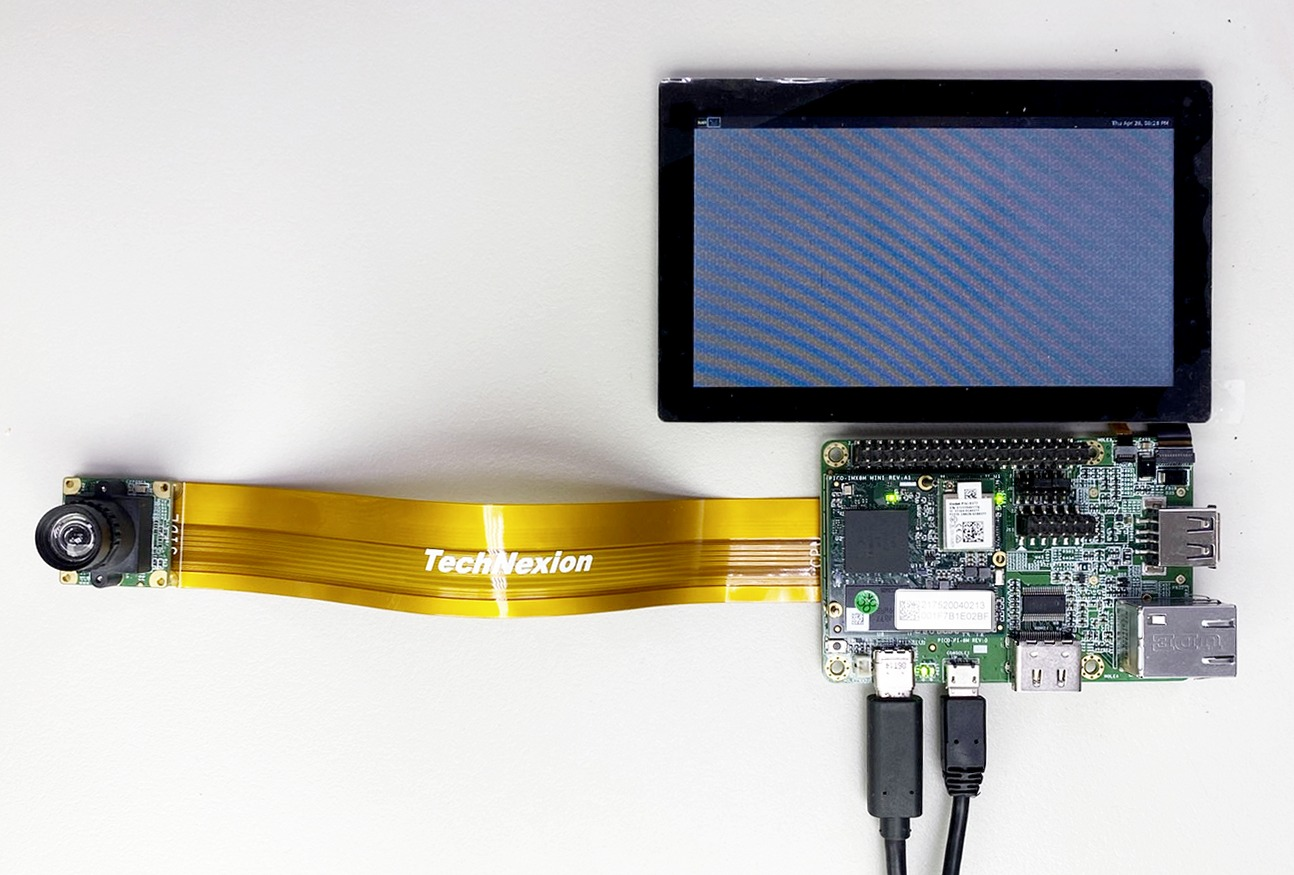
Overview
Connect debug console, power and camera to board
Prepare DC 5V power cable to plug in. (Note: PICO-PI-8M is powered by USB Type C)
Prepare UART cable connect to debug console of PICO-PI-8M.
It's recommended to prepare a FPC cable to connect board will be more easy to use.

Prepare Yocto demo image for testing TechNexion camera
The demo image contains the required device tree blobs and camera drivers to enable TechNexion cameras.
Prebuilt demo images can be available for download via TechNexion's server.
Image Download Link:
Supported Release List
You can find the prebuilt images page in Release Notes, take YP4.2 2024Q3 for example:.png "image(108).png")
Flash image to e.MMC
Using 'uuu' to flash
UUU
boot mode
Ensure the boot mode is configured as serial download mode.
Boot Configurations of PICO-PI-IMX8M-MINI
Using u-boot's 'ums' Command to Write Flash Storage over USB-OTG
UMS
u-boot
The board must also boot from either e.MMC with a version of U-boot that has the ums command enabled.
Please refer to Instructions for testing camera section for camera testing steps.
Build Yocto
Supported TechNexion Linux kernel branch for TEVS camera modules.
Linux Kernel | branch |
|---|---|
6.1.55 | tn-imx_6.1.55_2.2.0-stable |
Instructions for testing camera
Specify camera DTBO in u-boot
Auto detect camera
If you are using TEVS cameras, you can skip this section because it have auto detect camera function in u-boot.
Connect debug console cable to PICO-PI-IMX8M-MINI.
Power on board , and enter u-boot prompt.
Specify camera dtb via 'dtoverlay' u-boot environment variable.
u-boot=> setenv dtoverlay tevsContinue boot process.
u-boot=> saveenv
u-boot=> boot
Start camera video stream via gstreamer
Specify the capture device you just get and start gstreamer to get video stream on screen:
$ gst-launch-1.0 v4l2src device=/dev/video0 ! video/x-raw, width=<res_w>,height=<res_h> ! imxvideoconvert_g2d ! waylandsink window-width=<x> window-height=<y> sync=falseimxvideoconvert_g2d
It must have to use or using videoconvert. Because IMX8MM doesn't have ISI to convert format.
Trouble shooting
Ensure camera device tree blob overlay(DTBO) is specified correctly in u-boot.
u-boot=> printenv dtoverlay
dtoverlay=tevs
We can check whether camera have been initialized correctly.
$ dmesg -t | grep tevs
tevs 1-0048: tevs_probe() device node: tevs@48
tevs 1-0048: Version:24.9.0.1
tevs 1-0048: Product:TEVS-AR0144, HeaderVer:3, MIPI_Rate:800
tevs 1-0048: probe success
Was this article helpful?