Kit Assembly of PICO-PI-IMX8M-MINI
- 01 Oct 2021
- 3 Minutes to read
- Print
- DarkLight
- PDF
Kit Assembly of PICO-PI-IMX8M-MINI
- Updated on 01 Oct 2021
- 3 Minutes to read
- Print
- DarkLight
- PDF
Article summary
Did you find this summary helpful?
Thank you for your feedback!
This guide provides instructions for how to properly install VOICEHAT, Wi-Fi antenna, camera module and display to the evaluation board and how to set up the cardboard stand. You can watch our video or read the article below. Please click here to buy an evaluation kit.
Connect the parts
Connect the parts in the following order. Note that some versions of the PICO-PI-IMX8M-MINI evaluation kit do not include the VOICEHAT, camera, multi-touch display, and/or cardboard stand. Do not power your board during the installation process.
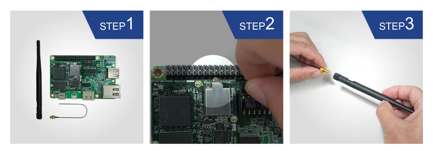
Wi-Fi antenna
Please follow the steps below to properly install the Wi-Fi antenna.
- Prepare Wi-Fi antenna, extender cable and development board.
- Locate the round antenna pin on the development board. Press the small round connector at the end of the extender cable onto this pin. You will need to press down until you hear a click sound. Make sure the MHF4 connector is aligned with the pin.
- Screw the extender cable into the base of the Wi-Fi antenna.

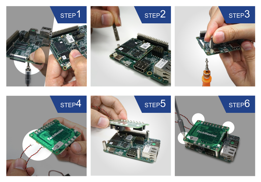
VOICEHAT
Please follow the steps below to properly install the VOICEHAT.
- Locate three module holes, insert screws into the holes. Place and tighten nuts on top. Then insert slowly the module and gently press into the development board to secure it.
- Then secure the module with screws.
- Locate four standoff holes, insert extender standoffs into the holes and screw standoffs on top.
- Connect Left and Right speakers to the VOICEHAT. Make sure the speaker cables exit on the left side.
- Align the 40-pin female connector next to the 40-pin expansion header on the development board and gently press the connector on the back of the VOICEHAT onto the header on the board.
- Then secure it with four screws.

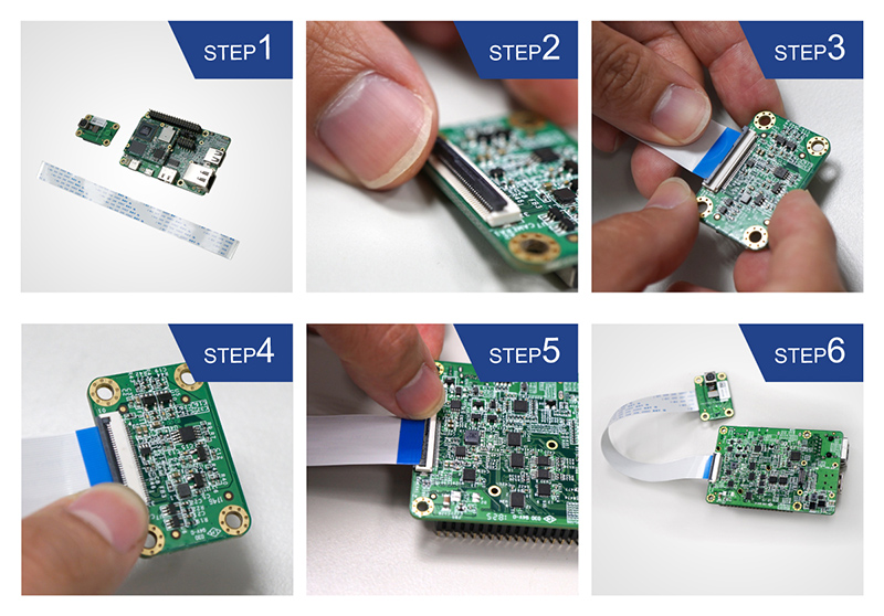
Camera module
Please follow the steps below to properly install the camera module.
- Prepare camera module, FPC cable and evaluation board. Turn the camera module over to reveal a white connector near the edge of the module.
- Swivel the black retaining clip upward.
- Insert either end of the camera module cable into the white connector. Make sure that the blue side of the ribbon is facing up and is aligned straight with the connector. The silver pins on the FPC cable should be facing down.
- Swivel the retaining clip back down to hold the FPC cable in place.
- Repeat these same steps with the other end of the cable and the connector on the board.

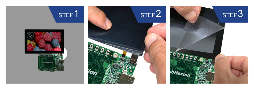
Display
Please follow the steps below to properly install the display.
- Locate the TOUCH and MIPI Display FPC connectors on the development board. Swivel the black retaining clips upward.
- Insert end of the TOUCH and MIPI Display FPC cables into the connectors on the board. The silver pins on the FPC cable should be facing down. Then swivel the retaining clips back down to hold the FPC cables in place.
- Remove the protective transparent film from the display.

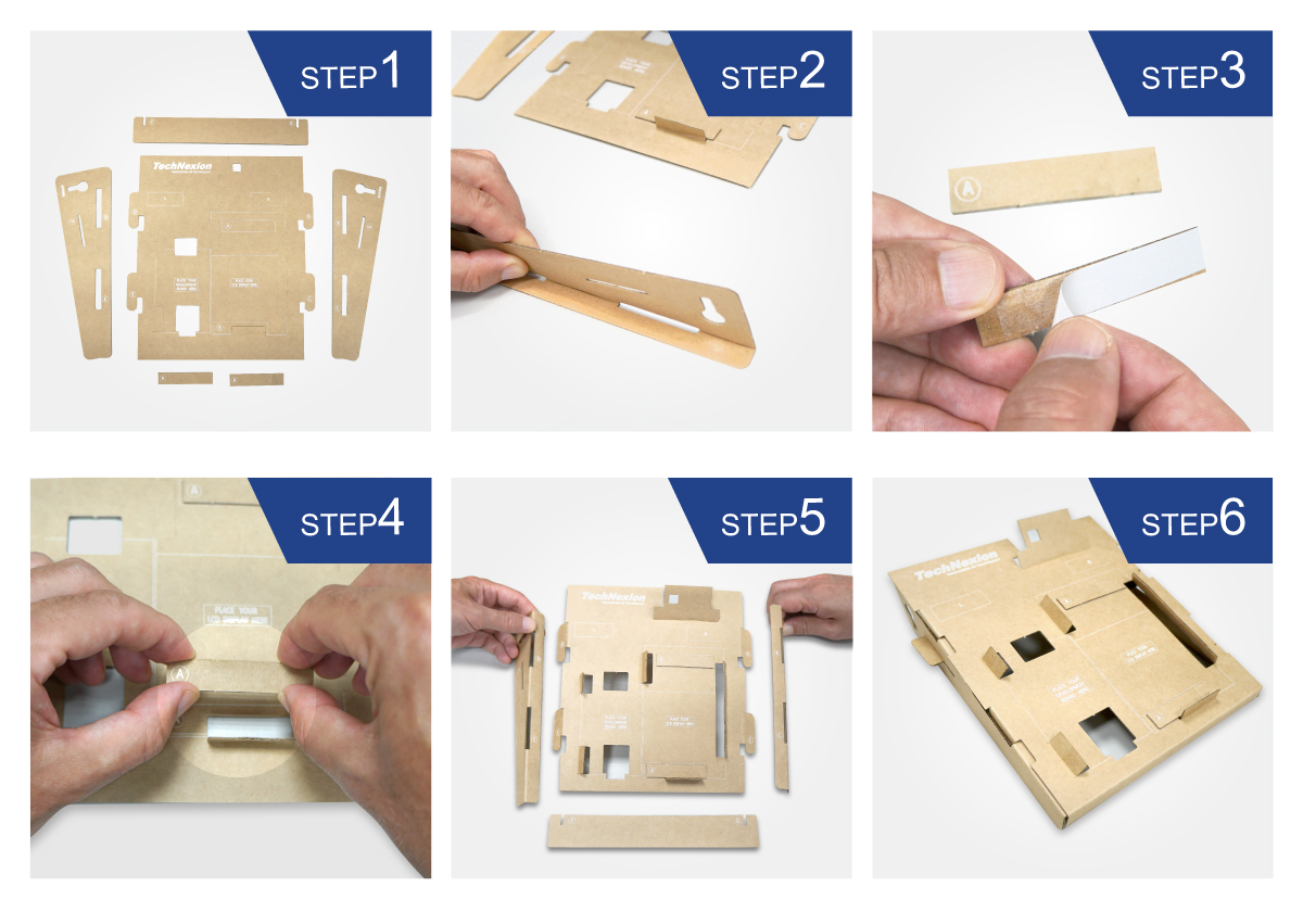
Cardboard stand
Time to set up the cardboard stand. It only takes a few minutes.
- Separate the shapes from the cardboard.
- Bend and fold the pieces along their scored lines.
- Remove the protective layer from the bottom of the A-lettered pieces.
- Gently press them into the matching space on the stand.
- Turn the stand upside down and insert the lettered tabs into the matching lettered slots.
- Turn the stand back and lift the tabs.

Final assembly steps
A few final steps before you can power up your kit.
- Insert the camera through the opening on the top side. Loop it around the back and to the top. Press the camera into the square opening. Reattach the FPC cable to the camera module.
- Adjust the antenna to a 90-degree angle. Insert it into the circular portion of the cutout and push it back until the joint is flush with the stand. Now push the antenna down for a snug fit. Reattach the extender cable to the antenna.
- Hold the display and board in front of the display and development board opening. Lower the display and board in position and gently press the edges into the stand. Connect the USB Type-C cable to power up the evaluation kit.
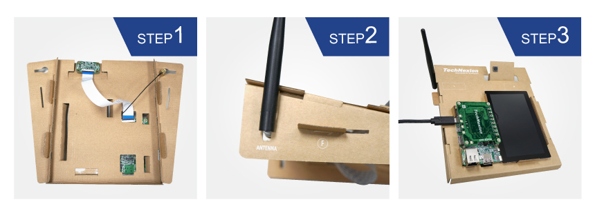

Congratulations, your development kit is now assembled!
Was this article helpful?