EDM-G-IMX8M TEVS Camera Usage Guide
- 24 Mar 2025
- 2 Minutes to read
- Print
- DarkLight
- PDF
EDM-G-IMX8M TEVS Camera Usage Guide
- Updated on 24 Mar 2025
- 2 Minutes to read
- Print
- DarkLight
- PDF
Article summary
Did you find this summary helpful?
Thank you for your feedback!
Introduction
This article guides you how to get started using TechNexion camera modules on EDM-G-IMX8M Plus/Mini Board.
Background knowledge needed
You must have the background knowledge to modify the kernel configuration, rebuild, and replace the kernel and the device tree source (DTS).
EDM-G-WB for example
Base on Yocto 4.2 (Mickledore) 2024Q2 Release this article will using EDM-G-WB baseboard for example. Previous versions before 3.3 can refer to this article. Other list of support board as below.
Supported Camera Modules
Camera Series | Products |
|---|---|
TEVS | TEVS-AR0144 |
VLS3 | VLS3-AR0144 |
TEVI-OV5640 and TEVI-AR Series Cameras is no longer supported from Yocto 4.2
TEVI-OV5640 and TEVI-AR Series Cameras are only supported up to Yocto 4.0. If you want to use them, you can refer to Yocto 4.0 (Kirkstone) 2024Q1 Release.
Supported EDM-G Boards
SoM | Board |
|---|---|
EDM-IMX8M-MINI | EDM-G-WB |
EDM-IMX8M-PLUS | EDM-G-WB |
Overview
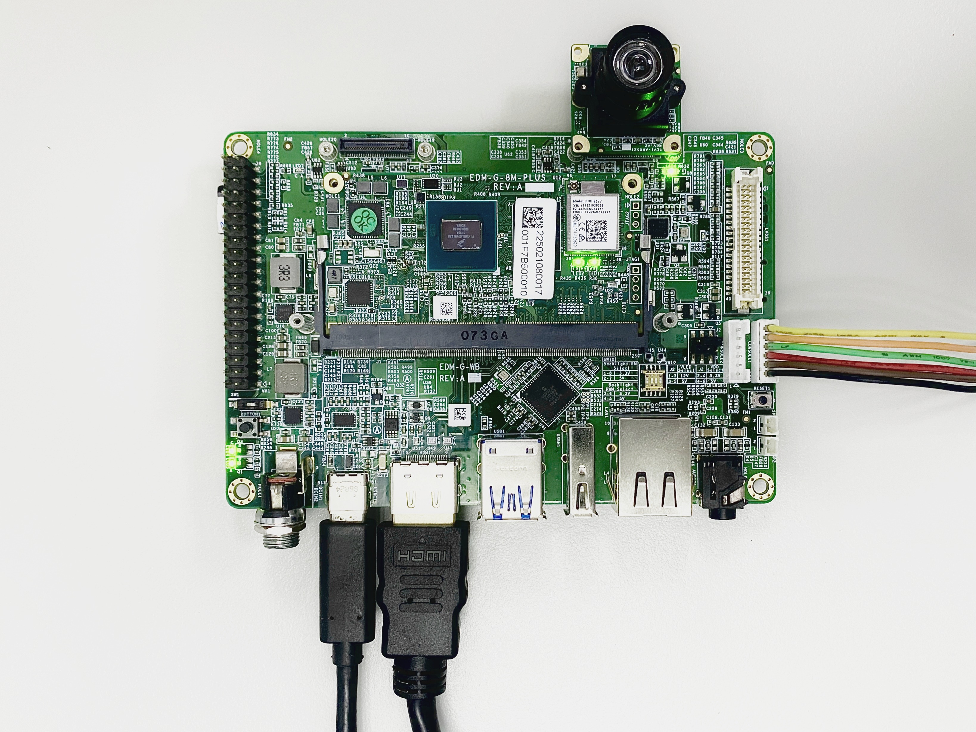
Connect debug console, power and camera to board
Prepare DC 5V/12V power cable to plug in. If using vizionlink must have DC 12V/minimum 3A power adapter by barrel jack connector.
(Note: EDM-G-WB 5V powered by USB Type C)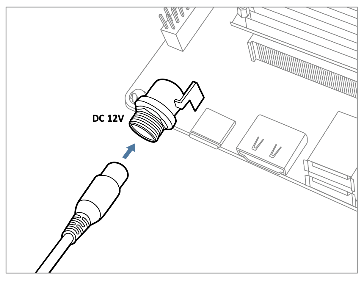
Prepare UART cable connect to debug console of EDM-G-WB.
There are two MIPI-CSI-2 connectors we refer to CSI1 and CSI2. These are 70-pin board-to-board connectors from Hirose. Below is a picture of TEVS camera with CSI1 connector shown.


Prepare Yocto demo image for testing TechNexion camera
The demo image contains the required device tree blobs and camera drivers to enable TechNexion cameras.
Prebuilt demo images can be available for download via TechNexion's server.
Image Download Link:
Supported Release List
You can find the prebuilt Images page in Release Notes, take YP4.2 2024Q3 for example:.png "image(106).png")
Flash image to e.MMC or SD Card.
Using 'uuu' to flash
UUU
boot mode
Ensure the boot mode is configured as serial download mode.
Boot Mode Selection of EDM-G-WB
Using u-boot's 'ums' Command to Write Flash Storage over USB-OTG
UMS
u-boot
The board must also boot from either e.MMC with a version of U-boot that has the ums command enabled.
Build Yocto
Supported TechNexion Linux kernel branch for TechNexion camera modules.
Linux Kernel | branch |
|---|---|
6.1.55 | tn-imx_6.1.55_2.2.0-stable |
Fetch Yocto source
Build Yocto (EDM-G-IMX8MP)
Build Yocto (EDM-G-IMX8MM)
Instructions for testing camera
Specify camera DTBO in u-boot
Auto detect camera
If you are using TEVI AR series or TEVS cameras, you can skip this section because it have auto detect camera function in u-boot.
Connect debug console cable to baseboard.
Power on board , and enter u-boot prompt mode.
(keep hit enter when the "Hit any key to stop autoboot : " is shown.)Specify camera dtb via 'dtoverlay' u-boot environment variable.
for TEVS Cameras:u-boot=> setenv dtoverlay tevsfor VLS3 Cameras:
u-boot=> setenv dtoverlay vlsContinue boot process.
u-boot=> saveenv
u-boot=> boot
Start camera video stream via gstreamer
We can check whether camera have been link via v4l2 control command:
$ v4l2-ctl --list-deviceGet the device number of camera capture device. As example we have camera on CSI1, that we can see /dev/video0 specify the capture device.
():
/dev/v4l-subdev0
():
/dev/v4l-subdev1
FSL Capture Media Device (platform:32c00000.bus:camera):
/dev/media0
mxc-isi-cap (platform:32e00000.isi:cap_devic):
/dev/video0
mxc-isi-cap (platform:32e02000.isi:cap_devic):
/dev/video1
Specify the capture device you just get and start gstreamer to get video stream on screen:
$ gst-launch-1.0 v4l2src device=/dev/video0 ! video/x-raw, width=<res_w>,height=<res_h> ! imxvideoconvert_g2d ! waylandsink window-width=<x> window-height=<y> sync=falseimxvideoconvert_g2d
It not necessary to use or using videoconvert. Because IMX8MP have ISI to convert format.
Trouble shooting
Ensure camera device tree blob overlay(DTBO) is specified correctly in u-boot.
For TEVS cameras:
u-boot=> printenv dtoverlay
dtoverlay=tevs
For VLS3 cameras:
u-boot=> printenv dtoverlay
dtoverlay=vls
We can check whether camera have been initialized correctly.
For TEVS cameras:
$ dmesg -t | grep tevs
tevs 1-0048: tevs_probe() device node: tevs@48
tevs 1-0048: Version:24.9.0.1
tevs 1-0048: Product:TEVS-AR0144, HeaderVer:3, MIPI_Rate:800
tevs 1-0048: probe success
mx8-img-md: Registered sensor subdevice: tevs 1-0048 (1)
mx8-img-md: created link [tevs 1-0048] => [mxc-mipi-csi2.0]
Ensure camera device tree blob(DTB) is specified correctly.
$ dmesg -t | grep -i model
Machine model: TechNexion EDM-G-IMX8MP and WB baseboard
Was this article helpful?